


Controlled Stop
In a controlled stop, drive motion is brought to a standstill in a controlled manner. The drive commands a zero velocity from the motor. The motor decelerates at the prescribed deceleration value (AXIS#.CS.DEC ).
A controlled stop can occur in the following ways:
- The user configures a programmable Action (see Actions Table) to perform a controlled stop.
- Either a controller or the user (through the WorkBench terminal window) initiates a software disable (AXIS#.DIS) command.
- CANopen Quick Stop. If the quick stop, bit 11 of the control word 6040h, 6840h Controlword - AxisX, is set, the axis will perform a quick stop. Object 605Ah, 685Ah Quick stop option code - AxisX configures what type of action is performed when the quick stop bit is set.
- A fault initiates a controlled stop from the drive. See Faults and Warning Messages for the faults which initiate a controlled stop.
- SSI or SS2 if the drive supports functional safety levels 2 or 3.
An implicit controlled stop is also part of some other features which stop motion:
- Homing processes which have multiple stages of motion.
- AXIS#.DISMODE = 2 and user executes AXIS#.DIS from the terminal or WorkBench disable buttons.
You must disable the drive in order to set AXIS#.DISMODE.
- A fault occurs which has a controlled stop (CS) reaction. After the CS is executed, the drive disables.
- Hardware limit switch: A digital input is defined as a positive or negative limit switch (AXIS#.HWLS.NEGSOURCE or AXIS#.HWLS.POSSOURCE). When the limit switch is met, the CS mechanism starts running. In this case, the parameter AXIS#.DISTO is not active.
- Software limit switch: SWLS defines an active software limit. When the limit is met, the CS mechanism starts running. In this case, the parameter AXIS#.DISTO is not active.
Use the drive CS parameters to configure a controlled stop as follows:
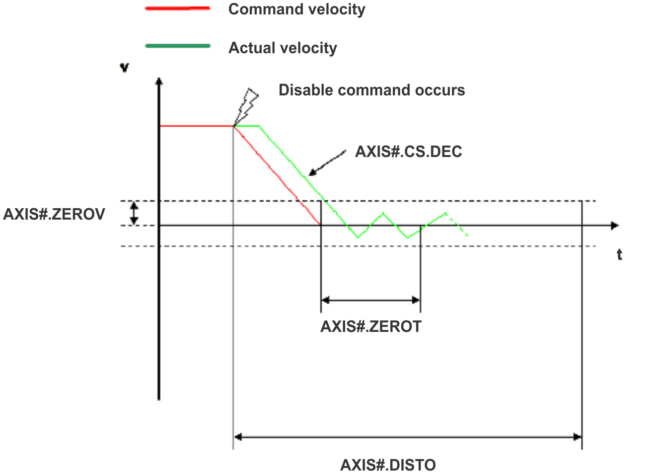
- AXIS#.CS.DEC : Deceleration ramp that is used for disable.
- AXIS#.ZEROV: Velocity 0 threshold. The motor shaft is considered as stopped as soon as the actual velocity (filtered through a 10 Hz filter, such as AXIS#.VL.FBFILTER ) is within ± AXIS#.ZEROV.
-
AXIS#.ZEROT: Velocity 0 time. The actual velocity must be consecutively within 0 ± AXIS#.ZEROV and the filtered acceleration < AXIS#.ZEROACC (If AXIS#.ZEROACC > 0) for the time AXIS#.ZEROT, before the drive completes the CS process. This value is used because the motor can overshoot out of the VEL0 window depending on the gains, deceleration ramp, motor inertia and so on.
- AXIS#.ZEROACC: Acceleration 0 threshold. If AXIS#.ZEROACC is set to zero, it will not be included in determining zero velocity. If it is set to a value greater than zero, the motor shaft is considered stopped as soon as the actual velocity (AXIS#.VL.FBFILTER) and filtered acceleration (AXIS#.VL.ACCFILTERED) are within threshold limits.
- AXIS#.DISTO : Disable time out. This parameter sets an overall and independent running check as to whether or not the drive can achieve the disable state. If the VEL0 window set in step 3 is too small, it is possible that the drive may never reach the end of the CS process. The AXIS#.DISTO parameter and functionality addresses this issue by disabling the drive after the AXIS#.DISTO time elapses, even if the CS process did not end.
Controlled Stop Diagram
When configuring the controlled stop feature, note the following:
- If the Hardware limit switch is active and any of the other CS activated, the only difference will be that in this case the AXIS#.DISTO will limit the time before disabling the drive.
- If the value of AXIS#.OPMODE is torque mode, the drive will activate dynamic brake instead of executing a controlled stop. This will help drive the axis to zero velocity even if an external force is being applied to the motor.
- Set AXIS#.DISTO to an appropriate value that will allow the motor to decelerate from any velocity to 0 with AXIS#.CS.DEC. This value must allow the motor’s velocity (AXIS#.VL.FB) and acceleration (If AXIS#.ZEROACC > 0) to afterward remain within ± AXIS#.ZEROV and AXIS#.VL.ACCFILTERED <= AXIS#.ZEROACC for the time period specified by AXIS#.ZEROT.
- If multiple controlled stop actions are active at the same time then the action with the highest priority will dominate. The priority from highest to lowest is ACTION#.TASK 10, 9 then 11.
- If multiple controlled stop actions are active at the same time then highest deceleration rate will be used.
- If a controlled stop input is removed before the axis has reached zero speed, the axis continues decelerating to zero and then disables if the controlled stop used requests a disable.
The drive issues a fault F6005 in case that the AXIS#.DISTO counter expires during a controlled stop procedure.
Related Topics


